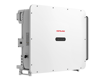
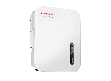
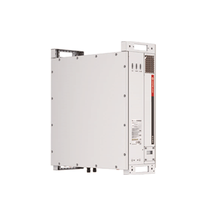
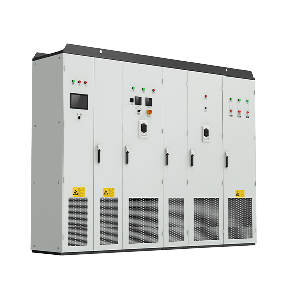
Item | Description and Technical Data |
Basic functions | Input voltage | 380 V (–15%) to 480 V (+10%), three-phase |
Input power frequency | (50 Hz/60 Hz)±5% |
Input voltage unbalance | ≤ 3% |
Output voltage | 0 V to input voltage |
Input frequency resolution | Digital signal precision 0.01 Hz and analog signal precision 0.01 Hz |
Output frequency | 0 Hz to 1500 Hz |
Motor type | Asynchronous motor, permanent magnet synchronous motor |
Control mode | V/F, OLVC, CLVC |
Speed range | 1:10 V/F; 1:100 OLVC; 1:1000 CLVC |
Starting torque | VF: 100% (0.5 Hz); OLVC: 150% (0.5 Hz); CLVC: 200% (0 Hz) |
Torque accuracy | ≤ ±5% in vector control mode |
Torque ripple | ≤ ±5% in vector control mode |
Speed stability accuracy | OLVC: 0.2%; CLVC: 0.01% |
Torque response | ≤ 5 ms in vector control mode |
Acceleration and deceleration time | 0.0s to 3200.0s; 0.0 min to 3200.0 min |
Torque boost | 0.0% to 30.0% |
Overload capacity | G-type: 150% 1 min/5 min, 200% 3s/5 min |
| P-type: 110% 1 min/5 min, 150% 10s/5 min |
V/F curve | Linear type, multi-point type, V/F semi-separated mode, V/F fully separated mode |
Simple PLC and multiple speeds | 16-speed operation through control terminals |
Built-in PID | Easily built closed-loop process control system |
Overvoltage and overcurrent stall control | Automatically limits the current and voltage during operation, to prevent frequent trips caused by overcurrent or overvoltage |
DC braking | Startup DC braking, shutdown DC braking |
Speed tracking | Both asynchronous and synchronous motors support speed tracking; both vector control and V/F control support speed tracking. |
Personalized features | Automatic restart after a power failure | Enables the frequency converter to automatically resume operation after undergoing a power failure and restoration during operation |
Master-slave control | Controls two or multiple motors synchronously in master/slave mode |
Zero servo | Implements the simple zero servo function under CLVC, achieving hovering at zero speed |
Brake control | Controls the motor brake during startup and shutdown of the frequency converter |
Parameter copy | Supports backup and restoration of local user parameters |
| With an external keyboard, parameters can be copied between different machines. |
Keyboard up/down | Allows configuring keyboard up/down keys to different targets |
Operation resumption after automatic reset due to a fault | Allows configuring the frequency converter to resume operation after automatic reset due to a fault |
Brake usage rate | Allows configuring the frequency control for braking transistor activation and deactivation, achieving dual functions of both braking and braking transistor protection |
Energy-saving operation | When the motor operates under light or no load, the output voltage (motor flux) is reduced to decrease motor loss and lower the noise generated by the motor. |
Timed control | Set time range: 0–65000 in the unit of second, minute, or hour |
Fixed length control | Predetermined length control |
Sleep and wake-up | Implements sleep and wake-up functions in water supply applications |
Multi-motor switching | Two groups of motor parameters available to control the switching of two motors |
Multiple encoder types | Incremental, resolver, and absolute encoders |
Encoder redundancy mode | When the frequency converter equipped with an encoder runs under CLVC, if the encoder malfunctions, the frequency converter automatically switches to OLVC operation. |
Communication mode | Modbus RTU (standard); Profibus-DP, CANopen, Profinet IO, Modbus TCP/IP, EtherCAT, and EtherNet/IP (optional) |
Input and output functions | Analog input terminal | AI1 and AI2: 0 V to 10 V/0 (4) mA to 20 mA |
Digital input terminal | DI1–DI5, 5 programmable digital input terminals, featuring optocoupler isolation, compatible with drain/source input |
| DI5 supports high-speed pulse input, with the maximum input frequency of 100 kHz. |
Digital output terminal | 2 open collectors output; output voltage range: 0 V to 24 V; current load capacity: 50 mA |
| DO1 supports high-speed pulse output, with the maximum output frequency of 100 kHz. |
Analog output terminal | 1, 0 V to 10 V/0 (4) mA to 20 mA |
Relay output | 1, contact-type FormC, NO and NC available |
Communication terminal | 1-channel (A and B), supporting the RS485 communication cable |
Expandability
I/O terminal card (optional) | DI6–DI8: 3-channel programmable digital input, featuring optocoupler isolation, compatible with drain/source input |
| DO3: 1-channel open collector output |
| AI3: 1-channel analog input, supporting –10 V to +10 V |
| AO2, AO3: 2-channel analog output, supporting 0–10 V/0–20 mA |
| 1-channel relay output (NO + NC) |
| 1-channel motor temperature sampling, supporting PT100, PT1000, and KTY84 |
Environmental conditions | Altitude | No derating is required within the altitude of 1,000 m. The current must be derated by 1% for every 100 m rise when the altitude is in the range of 1,000 m to 3,000 m. |
Ambient temperature | –25°C to +40°C (derating is allowed at a temperature of 40°C to 55°C) |
Humidity | 15% to 95%, non-condensing |
Vibration | 3M3, IEC60721-3-3 |
Storage temperature | –40°C to +70°C |
Application sites | Indoor, without direct sunlight and free of flammable and corrosive gases, liquids, and conductive particles |
Installation method | Wall-mounted |
IP rating | IP20 |
Cooling mode | Air-cooled |
 Power Consumption & Industries
Light Industrial Machinery
Large Experimental Platforms
Rail Transit
Mining Machinery
Petrochemical Industry
Ferrous Metallurgy


 Français


