


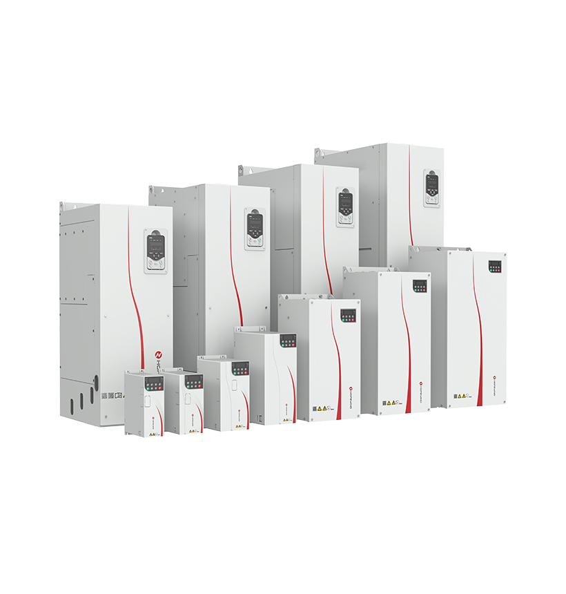
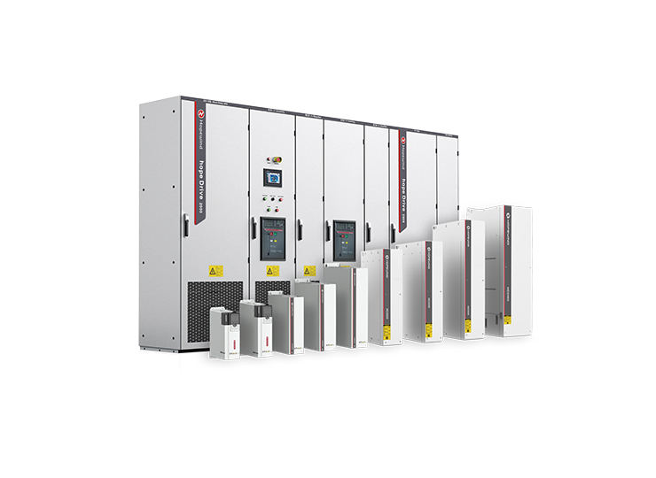
DC1500V Utility Inverter (HSHV506-G01)
PV Grid-Tied Inverter


| Projects | Specification Description and Technical Data | |
| Power input/ output | Input voltage | Input voltage: 380V (-15%) to 480V (+10%) Phase: Three-phase |
| Input power frequency | 50Hz/60Hz ±5% | |
| Input voltage imbalance | ≤3% | |
| Output voltage | 0V~Input voltage | |
| Output frequency | 0~600Hz | |
| Master control performance | Motor type | Asynchronous motor |
| Control mode | V/F, OLVC(Open-loop Vector Control) | |
| Speed range | 1:100 V/F; 1:200 OLVC | |
| Starting torque | OLVC: 150%(0.25Hz) | |
| Torque precision | ±5% (OLVC, above 5Hz) | |
| Torque ripple | ≤±5%, in Vector control mode | |
| Speed stability | OLVC, 0.2% | |
| Torque response | ≤5ms, in Vector control mode | |
| Acceleration/deceleration time | 0.0s~3200.0s; 0.0min~3200.0min | |
| Torque boost | 0.0%~30.0% | |
| Overload capacity | G type: 150% 1min/5min; 180%10s/5min; P type: 110% 1min/5min; 150% 10s/5min | |
| V/F curve | Straight-line type, multi-point type, V/F Half separation mode, V/F complete separation mode | |
| Input frequency resolution | Digital setting: 0.01Hz, Analog setting: maximum frequency ×0.025% | |
| Main functions | Acceleration/deceleration curve | Straight line and S-curve |
| Simple PLC, Multi-speed control | 16 speed segments supported through control terminals | |
| Automatic voltage regulation (AVR) | Automatically keeps the output voltage constant when grid voltage varies within a certain range | |
| Fixed length control | Control with given length | |
| Built-in PID | Easily forms a closed-loop control system | |
| Multi-motor switching | Switchover between two groups of motor parameters to control the two motors | |
| Virtual I/O | 8 groups of virtual VDI/VDO, 3 groups ofAI as DI, enabling simple logic control | |
| Overvoltage/Overcurrent stall control | Automatic current and voltage limitation during operation preventing the inverter from tripping due to frequent overcurrent or overvoltage | |
| Restart after power failure | After power failure and restoration, the inverter waits for a set time before automatically running | |
| Quick current limiting | Avoids frequent overcurrent faults in the inverter | |
| Power input/ output | Frequency setting method | Keypad; terminal UP/DOWN; multi-reference; pulse reference; communication |
| Analog input terminals | AI1; AI2: 0V~10V/ 0 (4)mA~20mA | |
| Digital input terminals | DI1-DI5, 5 programmable digital input terminals with opto-isolation, compatible with both sinking/sourcing inputs. DI5 supports high-speed pulse input with a maximum input frequency of 100kHz. | |
| Digital output terminals | Open-collector output; output voltage range: 0V~24V; current load capacity: 50mA. DO1 supports high-speed pulse output with a maximum output frequency of 100kHz. | |
| Analog output terminals | 1-channel 0V ~ 10V/0(4)mA ~ 20mA | |
| Relay output | 1-channel Form C contact, NO+NC | |
| Communication | Communication protocols | Modbus RTU (standard configuration); Profibus-DP; Profinet IO; CANopen; Modbus TCP/IP; Ethercat; EtherNet/IP (optional configuration) |
| Ambient requirements | Altitude | ≤1000m: no need for derating 1000~3000m: current derating by 1% per 100m increased |
| Ambient temperature | -25℃~+40℃ (Running with derating allowed between 40~55) | |
| Humidity | 15% ~ 95%, No condensation | |
| Vibration | 3M3, IEC60721-3-3 | |
| Storage temperature | −40°C~+70°C | |
| Installation place | Indoor, without direct sunlight, free from flammable, corrosive gases, liquids, and conductive particles. | |
| Optional accessories | Communication expansion card, I/O terminal expansion cards | |
| Protections | Protection against short circuit , overcurrent, overload, overvoltage, undervoltage, phase loss, overtemperature, external faults, etc. | |
| Installation method | Installed in a cabinet | |
| Protection rating | IP20 | |
| Cooling method | Air cooling | |
Business E-mail:
Globalsupport@hopewind.com
Service E-mail:
Globalservice@hopewind.com


 English
 中文
中文 Français
 Deutsch
 한국어
한국어 Nederlands
 Polski
 Português(BR)
 Pусск(KZ)
 Türkçe