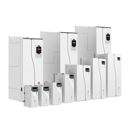
| Item | Description and Technical Data |
| Power input and output | Input voltage | 380 V (–15%) to 480 V (+10%), three-phase |
| Input power frequency | 50 Hz/60 Hz±5% |
| Input voltage unbalance | ≤ 3% |
| Output voltage | 0 V to input voltage |
| Output frequency | 0–600 Hz |
| Main control performance | Motor type | Asynchronous motor, synchronous motor |
| Control mode | V/F, OLVC, CLVC |
| Speed range | 1:10 V/F; 1:100 OLVC; 1:1000 CLVC |
| Starting torque | OLVC: 150% (0.5 Hz); CLVC: 200% (0 Hz) |
| Torque accuracy | ≤ ±5% in vector control mode |
| Torque ripple | ≤ ±5% in vector control mode |
| Speed stability accuracy | OLVC: 0.2%; CLVC: 0.01% |
| Torque response | ≤ 5 ms in vector control mode |
| Acceleration and deceleration time | 0.0s to 3200.0s; 0.0 min to 3200.0 min |
| Torque boost | 0.0% to 30.0% |
| Overload capacity | 150% 1 min/5 min, 180% 10s/5 min |
| V/F curve | Linear type, multi-point type |
| Input frequency resolution | Digital signal precision 0.01 Hz and analog signal precision 0.01 Hz |
| Specialized functions | Anti-swing function | Prevents large-scale swings of the load during acceleration or deceleration, thereby avoiding accidents. |
| Anti-slack rope protection | Enables the frequency converter to speed up the lifting tool slowly for smooth ascent based on the detection of a heavy load |
| Hook slip protection | Detects whether the heavy load is slipping and issues an alarm after the brake engages, thereby causing the motor to hover |
| Brake control | Controls the engagement and disengagement of the brake device based on factors such as frequency and current, to prevent unexpected slipping |
| Operating rod zero-return detection | Determines whether the operating rod is in the neutral position |
| Reverse control of commands | Supports either engaging the brake to halt during forward and reverse rotation switching, or continuing directly to the reverse frequency without engaging the brake, when brake control is active |
| Acceleration and deceleration switching | Supports up to three frequency switching points and the adjustment of acceleration time and deceleration time |
| Deceleration limit | Supports simple positioning, automatically optimizing deceleration time |
| Voltage suppression | Automatically adjusts the frequency to stabilize the bus voltage, preventing fault reports |
| Overload protection | Prevents equipment damage due to excessive load |
| Low-speed operation protection | Primarily protects machines that should not operate at low speeds for a long time |
| Load-dependent speed regulating | Automatically adjusts the operating speed based on load changes, raising work efficiency |
| Macro parameters | Selects different hoisting macros based on the on-site application scenario and hoisting mechanism. |
| Basic functions | Acceleration and deceleration curves | Straight line, S-shaped curve |
| Simple PLC and multiple speeds | 16-speed operation through control terminals |
| Master-slave control | Controls two or multiple motors synchronously in master/slave mode |
| Automatic voltage regulation (AVR) | Constant output voltage when the grid voltage changes within a certain range |
| Multi-motor switching | Four groups of motor parameters available to control the switching of four motors |
| Overvoltage and overcurrent stall control | Automatically limits the current and voltage during operation, to prevent frequent trips caused by overcurrent or overvoltage |
| Automatic restart after a power failure | Enables the frequency converter to automatically resume operation when the set time is reached, after the frequency converter undergoes a power failure and restoration |
| Fast current limit | Prevents frequent faults on the frequency converter caused by overcurrent |
| Power input and output | Frequency setting methods | Through the operation panel, up/down terminals, multi-speed settings, terminal pulse settings, and communication |
| Analog input terminal | AI1 and AI2: 0 V to 10 V/0 (4) mA to 20 mA |
| Digital input terminal | DI1–DI5, 5 programmable digital input terminals, featuring optocoupler isolation, compatible with drain/source input |
| DI5 supports high-speed pulse input, with the maximum input frequency of 100 kHz. |
| Digital output terminal | Open collector output; output voltage range: 0 V to 24 V; current load capacity: 50 mA |
| DO1 supports high-speed pulse output, with the maximum output frequency of 100 kHz. |
| Analog output terminal | 1, 0 V to 10 V/0 (4) mA to 20 mA |
| Relay output | 1, contact-type FormC, NO and NC available |
| Communication | Communication protocol | Modbus RTU (standard); Profibus-DP, Profinet IO, CANopen, Modbus TCP/IP, Ethercat, and EtherNet/IP (optional) |
| Operating environment | Altitude | No derating is required within the altitude of 1,000 m. The current must be derated by 1% for every 100 m rise when the altitude is in the range of 1,000 m to 3,000 m. |
| Ambient temperature | –25°C to +40°C (derating is allowed at a temperature of 40°C to 55°C) |
| Humidity | 15% to 95%, non-condensing |
| Vibration | 3M3 standard: 0.75–110 kW; 2 Hz ≤ f < 9 Hz: displacement of 1.5 mm; 9 Hz ≤ f < 200 Hz: accelerated speed of 5 m/s2 |
| 3M5 standard: 132–400 kW; 2 Hz ≤ f < 9 Hz: displacement of 3 mm; 9 Hz ≤ f < 200 Hz: accelerated speed of 10m/s2 |
| Storage temperature | –40°C to +70°C |
| Application sites | Indoor, without direct sunlight and free of flammable and corrosive gases, liquids, and conductive particles |
| Optional accessories | Code disc card, communication expansion card, I/O terminal expansion card |
| Protection functions | Protection against short circuit, overcurrent, overload, overvoltage, undervoltage, phase loss, overheat, and external fault |
| Installation method | Installed inside a chassis or cabinet |
| IP rating | IP20 |
| Cooling mode | Air-cooled |
 Power Consumption & Industries
Light Industrial Machinery
Large Experimental Platforms
Rail Transit
Mining Machinery
Petrochemical Industry
Ferrous Metallurgy



 Français